Data Asset
The Pipe Builder Data Asset centralizes all static meshes and parameters that control the Pipe Builder Actor’s appearance—loops, corners, junctions, supports, material presets, and component settings. Decoupling this data from the actor enables consistent styling across multiple networks and quick visual iteration through asset swapping, with no actor edits required.
Below is a full list of parameters.
General Reference
| Variable | Default | Description |
|---|---|---|
| Pipe Mesh Type | ISM | Component type used for all pipe meshes. • StaticMesh – Simple static mesh component.• ISM – Instanced Static Mesh; recommended for Nanite assets without LODs.• HISM – Hierarchical Instanced Static Mesh; identical to ISM but supports per instance LODs. |
| Pipe Cull Distance | (0, 0) | ISM and HISM only X = start, Y = end cull distances. |
| Pipe Max Draw Distance | 0.0 | Default maximum draw distance for all pipe meshes. 0.0 = infinite. |
| Pipe Collision Profile | – | Default collision profile applied to every mesh component. |
| Mobility | Movable | Mobility setting for the root spline component and all attached child components. |
| Generate Overlaps | false | When enabled, all pipe meshes raise overlap events. Note: For ISM/HISM, bMultiBodyOverlap is automatically set to true. |
| Cast Shadows | true | Shadow casting toggle for every pipe mesh. |
Material Presets
The material preset system uses an array of presets, where each preset can contain any number of material entries, allowing for rapid switching between different material setups. Each entry consists of a slot name and a material. This is especially useful when switching between static meshes with different slot orders—using slot names instead of raw indices ensures materials are applied correctly. Slot names also enable custom material behavior for pipes, such as overriding specific corners, junctions, or support meshes, while still preserving default behavior where needed.
To change a specific mesh and assign a custom material, follow the steps below.
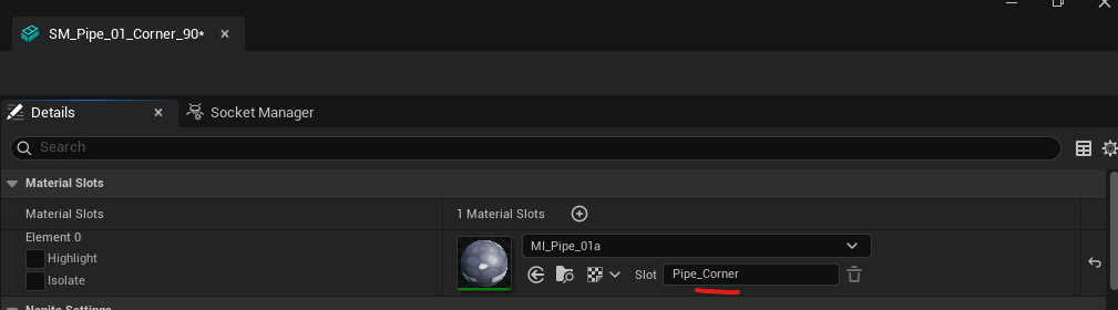
Change Slot Name
Open the static mesh editor for the desired mesh, go to the Details tab, select the target material, and change the default slot name (e.g., to Pipe_Corner).
Add Entry to Preset
Open the Pipe data asset where the mesh is located. Navigate to Material Presets, press the + button on an existing preset or create a new one. Enter your custom slot name and assign a custom material. To replicate default plugin behavior, simply use the same material as the default.
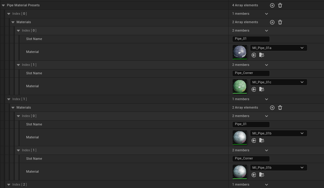
This system allows you to override any mesh in the plugin—each preset can contain any number of entries while still supporting the single-material default behavior.
Loop Meshes
| Variable | Default | Description |
|---|---|---|
| Pipe Loop Meshes | Empty | Collection of static meshes representing straight pipe segments. Each entry includes a weight (0–100) controlling selection probability. |
| Pipe Loop Scale Range | (0.75, 1.25) | X = minimum, Y = maximum, allowed scale on X axis. Clamped to 0.2–3.0. |
Corners
| Variable | Default | Description |
|---|---|---|
| Pipe Corner Spline Meshes | Empty | Static meshes used in Bent corner mode. Each entry includes a probability weight (0–100). |
| Pipe Corner Meshes | Empty | List of static meshes which used for Fitted corner mode. Each entry includes an Angle variable. |
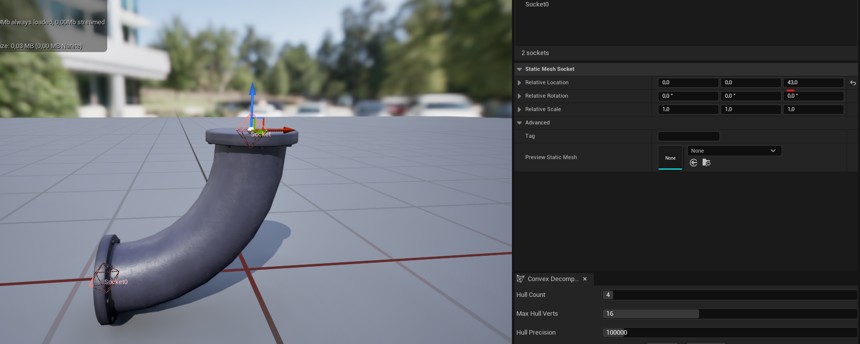
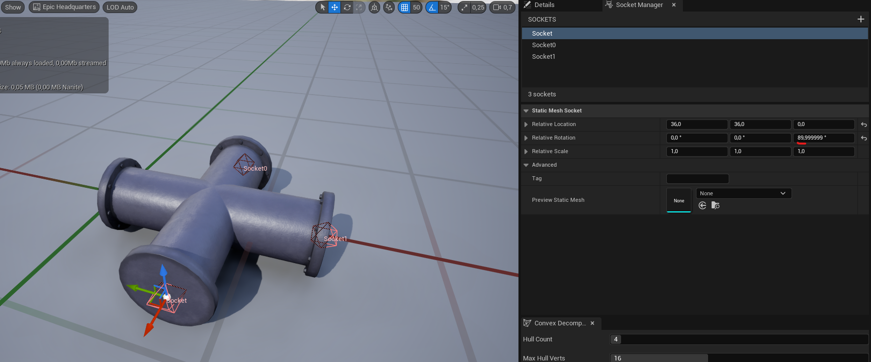
Socket Requirements for Fitted Corners
Every fitted corner mesh must define two sockets—one at the start and one at the end. These sockets determine connection points for adjacent segments.
To create sockets follow the steps below.
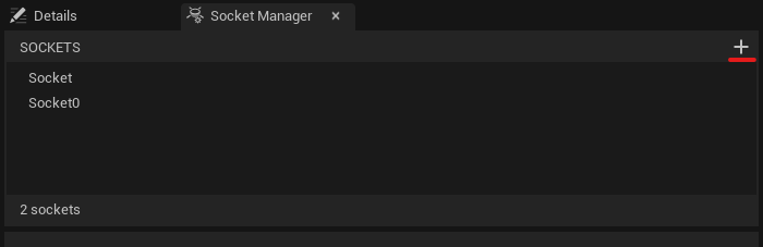
Add Socket
Navigate to the Socket Manager tab within the Static Mesh Editor and click the + button to create a new socket.
Define Socket Transform
Position and orient the socket using the viewport manipulator or by entering precise values in the Details panel.
Corner Splits
The Corner Splits parameter determines the angular granularity of the pipe system. It defines how many subdivisions are created within a quadrant, establishing “Selection Zones” that map target angles to specific static meshes.
Default: 2
Valid values: 1, 2, 4, 8, 16 (must be a power of two)
Split 2: 45° Granularity (Default)
Requires three unique corner meshes:45°, 90°, and 135°
    pie title Split 2 (45° Increments)
    "45° Mesh Zone" : 45
    "90° Mesh Zone" : 45
    "135° Mesh Zone" : 45
    "Straight (180°)" : 45
    "Remaining Circle" : 180
Split 4: 22.5° Granularity
Requires seven unique corner meshes:22.5°, 45°, 67.5°, 90°, 112.5°, 135°, 157.5°
This allows for high-precision snapping in complex routing.
    pie title Split 4 (22.5° Increments)
    "22.5° Zone" : 22.5
    "45.0° Zone" : 22.5
    "67.5° Zone" : 22.5
    "90.0° Zone" : 22.5
    "112.5° Zone" : 22.5
    "135.0° Zone" : 22.5
    "157.5° Zone" : 22.5
    "Straight (180°)" : 22.5
    "Remaining Circle" : 180
| Split Value | Increment | Required Corner Meshes (up to 180°) | Snap Window (±) |
|---|---|---|---|
| 1 | 90° | 90° | 45.0° |
| 2 | 45° | 45°, 90°, 135° | 22.5° |
| 4 | 22.5° | 22.5°, 45°, 67.5°, 90°, 112.5°, 135°, 157.5° | 11.25° |
Bend Correction
Bend Max Correction Angle is a threshold (in radians) for correcting the up‑vector on bent corners. Prevents abrupt mesh twisting when consecutive point directions are nearly parallel.
Note: Rarely requires adjustment.

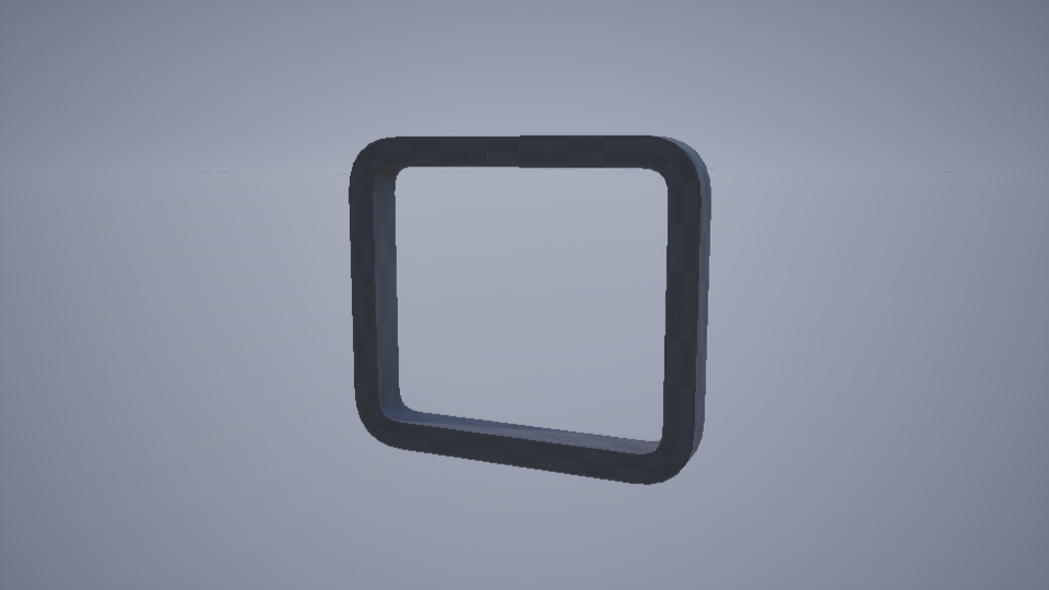
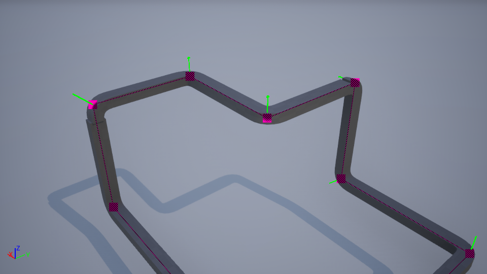
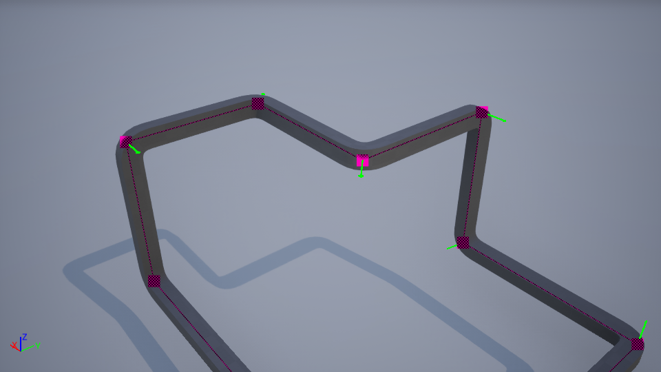
Correct Corner Rotation is enabled by default. It automatically computes a custom up‑vector at corner points to eliminate twisting in bent mode, particularly noticeable on non‑square pipe profiles. Round or perfectly square profiles mask this correction entirely.
Below is an example of the issue.
Junctions
Junction Meshes is a collection of meshes used for endpoints and segment points. Though primarily for junctions, they can double as simple caps when placed at endpoints.
Loopable: If true, the mesh may appear at interior segment points; if false, it is restricted to start/end points.
Mesh: The static mesh asset.
Every junction mesh intended as a branch point must include sockets at each endpoint.
Support Meshes
Support Meshes is a collection of static meshes used for generating support structures. Each entry includes a probability weight (0–100).
Editor-Only Variables
| Variable | Default | Description |
|---|---|---|
| Text Height | 50.0f | Debug text height |
| Text Size | 50.0f | Debug text size |
| Preview Connection Mesh | PreviewMesh | Static mesh used for visual previews. |
| Preview Mesh Scale | 1.0f | Uniform scale applied to the preview mesh. Clamped at 0.01 |