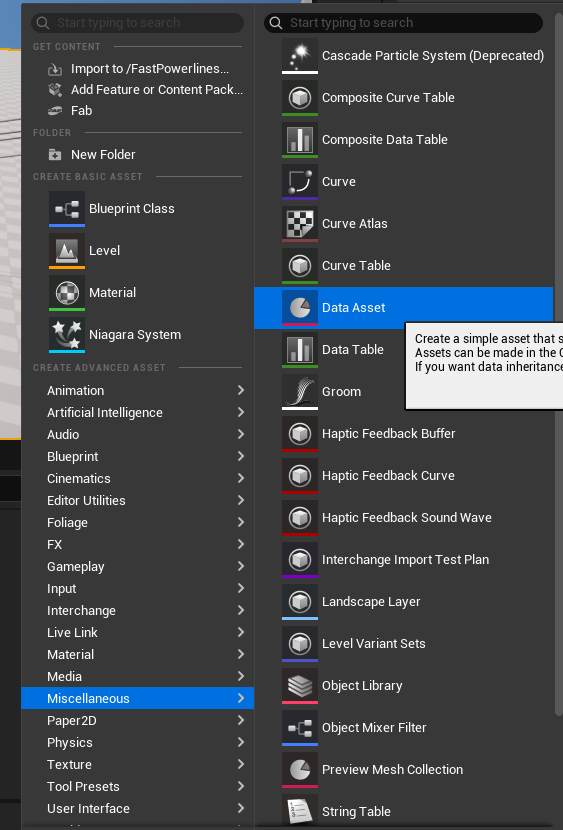
Data Asset
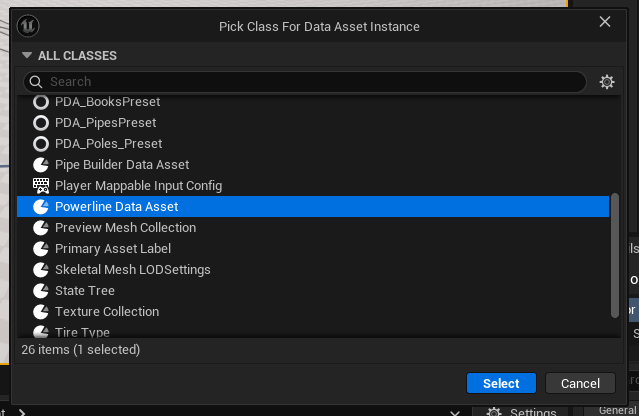
The Powerline Data Asset serves as a centralized configuration container that stores static properties for powerline systems. By separating this data from the actor itself, it enables efficient management, rapid prototyping, and easy sharing of settings across multiple powerline instances in your project. The asset is organized into two sections:
- Powerline
- Cable (containing cable-specific properties).
Powerline Reference
Below is a complete list of all powerline related properties.
Poles
The Pole Array defines the library of static meshes which are used as support meshes. Includes weighted probability that controls how often each mesh is selected during generation.
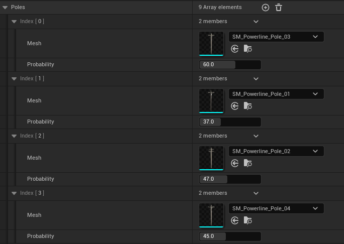
The powerline actor uses a random stream to select meshes based on these weights, weight value in range of 0-100 that determines its likelihood of being chosen. A value of 0 completely excludes the mesh from selection.
You can add any number of mesh entries.
Sockets
Static mesh sockets serve as the primary connection points for cable generation. Cables are automatically created between matching sockets on consecutive poles within the powerline system.
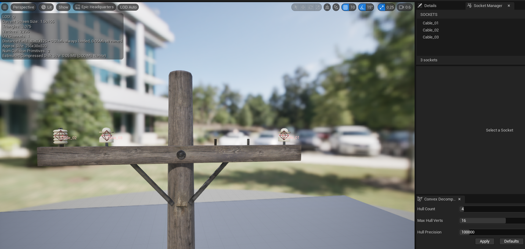
To add a custom socket to a static mesh for cable generation, follow these steps:
Add Socket
Navigate to the Socket Manager tab within the Static Mesh Editor and click the + button to create a new socket.
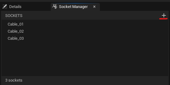
Configure Socket Name
Rename the socket from its default name to something descriptive and consistent, such as Cable_01 or Cable1.
Set Socket Transform
Position and orient the socket using the viewport manipulator or by entering precise values in the Details panel.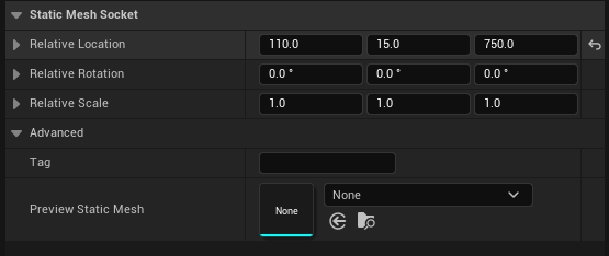
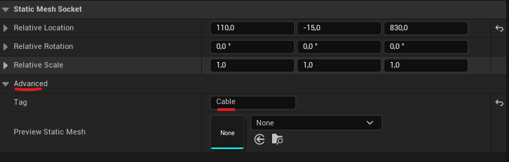
Add Socket Tag
Click the Advanced menu, find the tag variable, and enter Cable or cable.
Powerline Properties
Mesh Type
- Static Mesh: Places a standard static mesh at each spline point.
- Spline Mesh: Deforms the mesh at a spline point using start and end tangents.
- ISM: Places an instanced static mesh component at each spline point. Same as HISM, could be usefull with
Nanitemeshes. - HISM: Places an hierarchical instanced static mesh component at each spline point.
This is a good way to optimize draw calls when pole mesh variation is low.
| Variable | Default | Description |
|---|---|---|
| Mobility | Movable | Global actor mobility. All generated components inherit this mobility type per Unreal requirements. |
| Spline Mesh Axis | X | Spline Mesh only. Defines which local mesh axis aligns with the spline direction. |
| Cull Distance Start End | 0,0 | ISM and HISM only. Maximum cull(render) distances for an instanced pole mesh. X = start, Y = end. |
| Base Pole Yaw | 0° | Global rotation applied to all poles around the vertical (Z) axis. Useful for correcting imported meshes that are not oriented to the desired world alignment. |
| Pole Material Presets | Empty | An array of material presets. Each preset is itself an array of materials to apply to the pole meshes. • Each material’s slot name must match a static mesh material slot. • This system allows switching between different materials (presets), each of which can configure one or more material slots on the mesh. |
| Pole Max Draw Distance | 0 | Maximum render distance for pole meshes. Set to 0 for infinite draw distance. |
| Pole Collision Profile | BlockAll | Physics collision profile assigned to pole meshes. |
| Generate Overlaps | false | Enables overlap events for pole meshes when set to true. |
| Cast Shadows | true | Controls whether poles and cables cast dynamic shadows. |
Cable Reference
Below is a complete list of all cable properties.
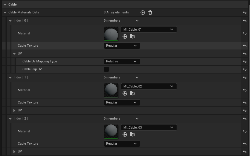
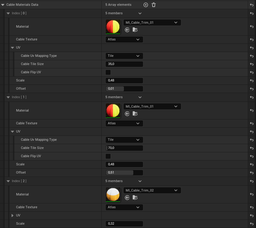
Materials
Cable materials data is a customizable struct that serves as a container for cable UVs and materials, offering full control over generated cable UVs. Each entry can be selected randomly or manually by the powerline actor.
Atlas mode enables offsetting and scaling on the minor axis, allowing trim or atlas textures to reduce draw calls. Unique materials each add a mesh section to the procedural cable mesh, incurring an extra draw call. However, the same material used across different entries with varying UV parameters will be batched into a single mesh section.
Materials are also useful for default powerlines to create randomized wind effects.
| Variable | Default | Description |
|---|---|---|
| Texture | Regular | Switches between regular and atlas modes. Regular: a standard tiled texture. Atlas: for tiled trim textures, allows manipulation of UVs on the minor axis. |
| Mapping | Relative | Relative: maps UVs based on cable length using the spacing value. Tile: allows independent control of texture tiling regardless of cable spacing. |
| Tile Size | 40 | Controls the scale of texture tiling along the cable length in Unreal units (only affects Tile mapping type). |
| Flip UV | false | Swaps UV orientation between vertical (Y) and horizontal (X) axes. Default uses Y-axis (vertical) alignment, matching the example textures. Useful for rotated source textures. |
| Scale | 1.0 | Allows scaling of cable UVs on the minor axis. Minimum value is 0.01. |
| Offset | 0.0 | Allows offsetting of cable UVs on the minor axis. Clamped to -1 to 1. |
Wind
Wind properties are designed specifically for use with a dedicated cable material and are stored in the vertex colors of the cable mesh.
EnableWind variable to false (default is true).| Channel | Description |
|---|---|
| R (Red) | Wind mask – calculated from contrast, sharpness, and intensity properties to define where wind deformation occurs. |
| G (Green) | Random time offset – a per-cable random value (0–1) added to the wind animation time to create variation. |
| B (Blue) | Random strength modifier – a per-cable random value (0–1) used to interpolate between minimum and maximum wind strength values. |
Visualization of all vertex color channels: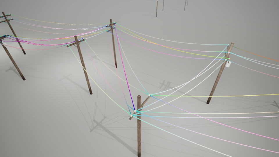
Random values in G and B channels: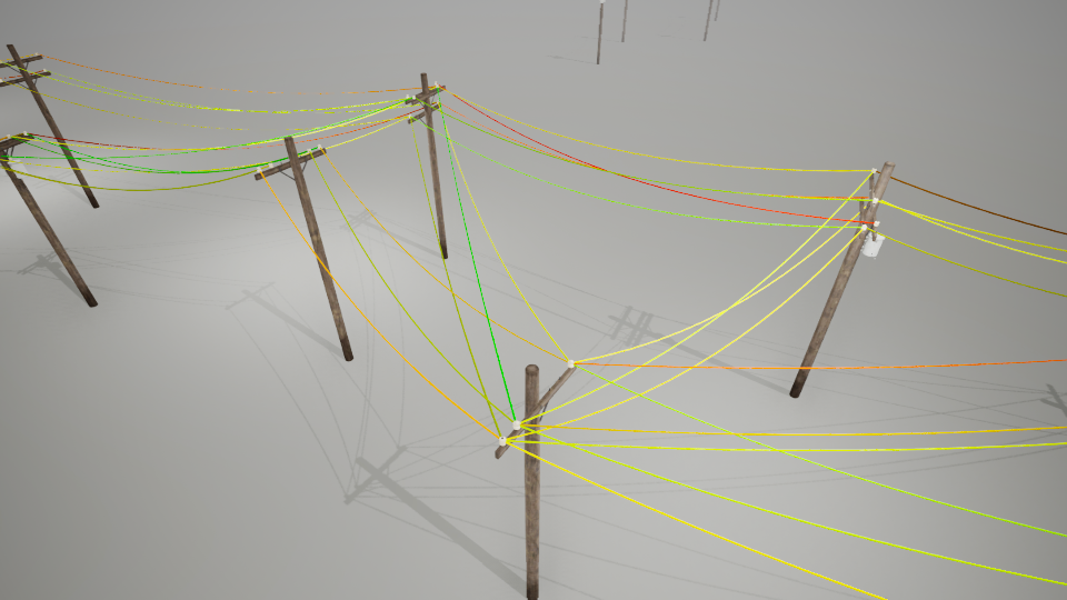
Wind Mask Properties
Wind Contrast – Amplifies the wind effect by multiplying both strength and sharpness values. Provides additional control over wind definition.
Wind Sharpness – Controls the falloff gradient of the wind effect from cable endpoints toward the center. Higher values create a more abrupt transition.


Wind Intensity – Global multiplier for the final wind effect. Combines the data asset intensity with the powerline actor’s global wind intensity setting.

Cable Properties
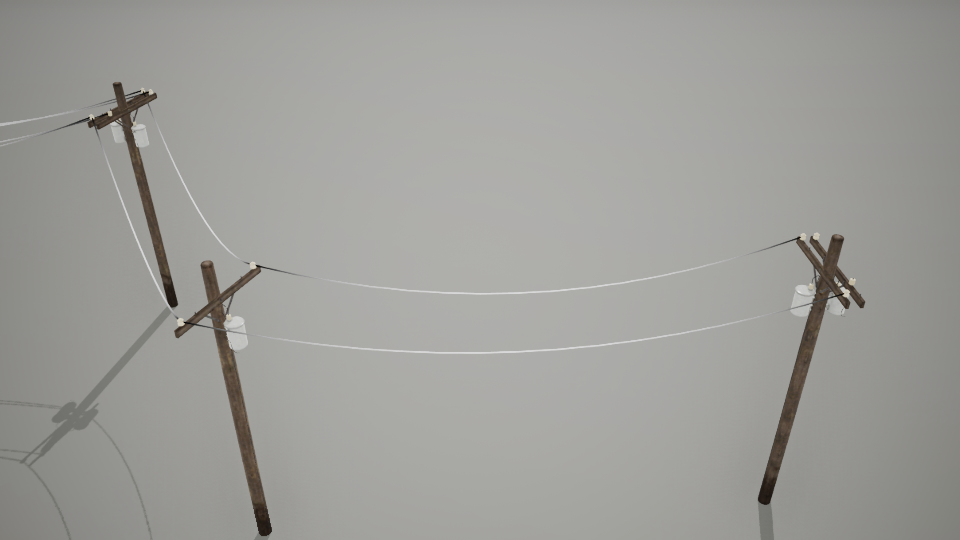
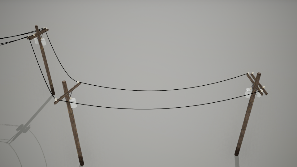
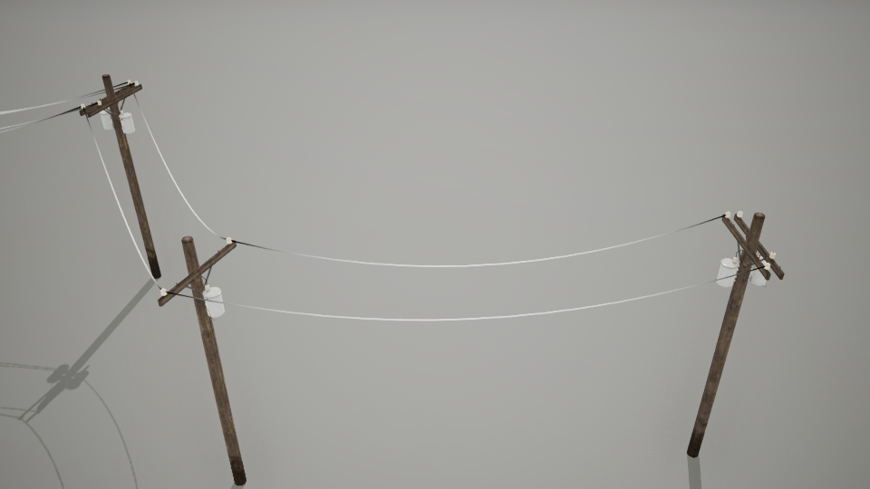
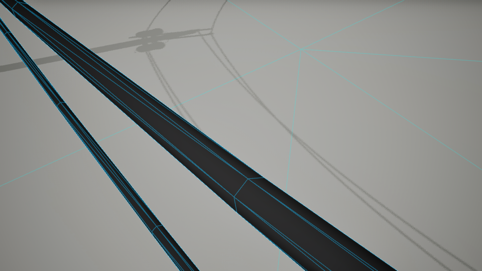
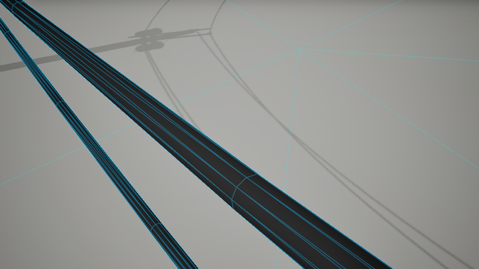
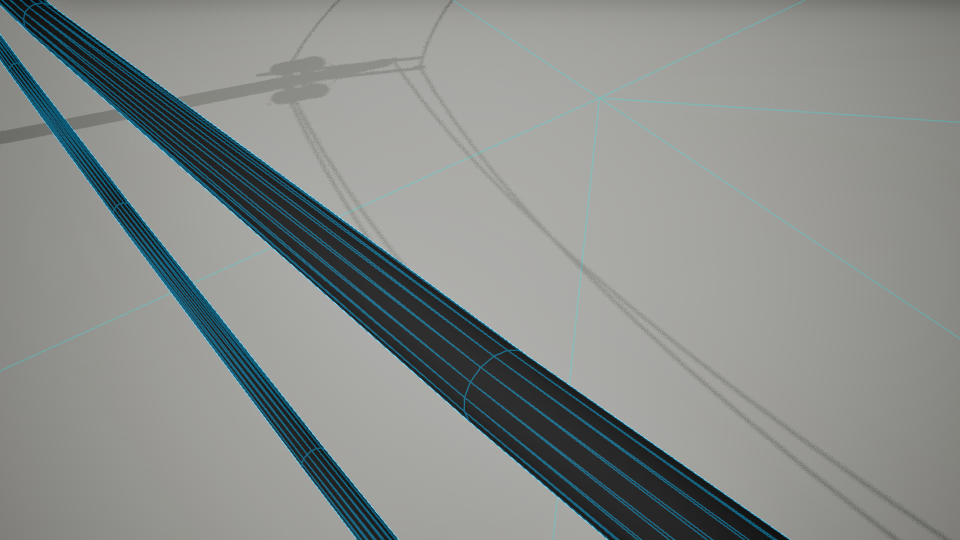
Cable Sides
Controls the number of radial segments around each cable, directly affecting mesh smoothness, performance, and vertex count.
- Minimum: 3 sides (creates a triangular cable cross-section)
- Maximum: Clamped to 16 sides
- Default: 4 sides (produces a square cross-section that looks appropriate for default powerlines)
Visual Comparison:
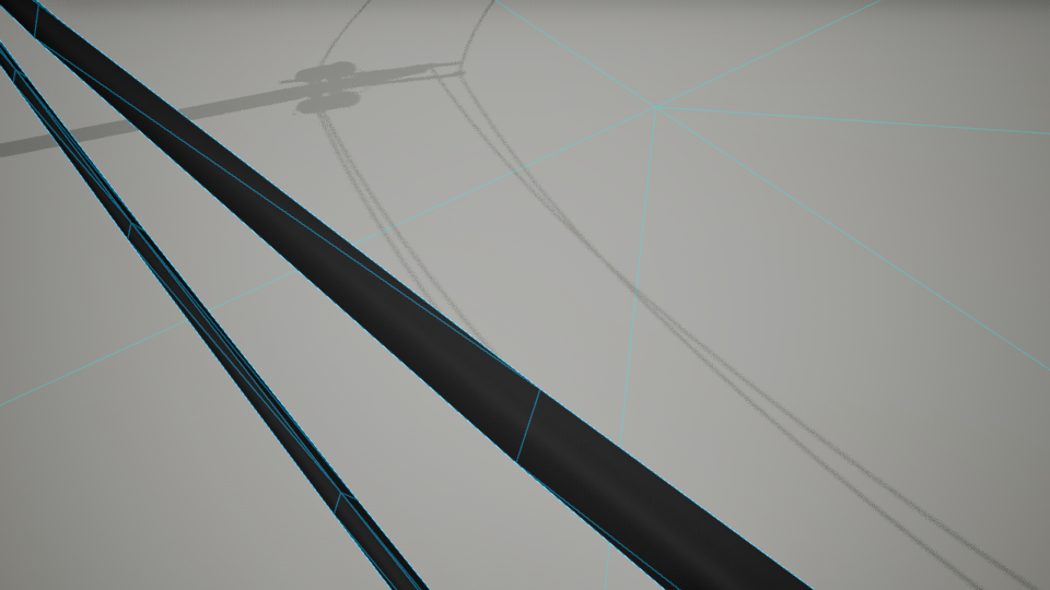
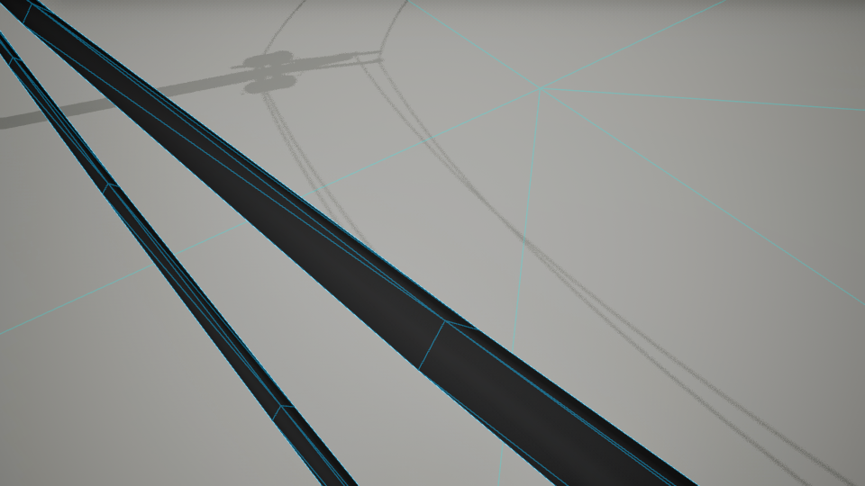
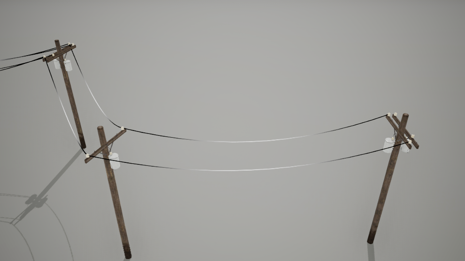
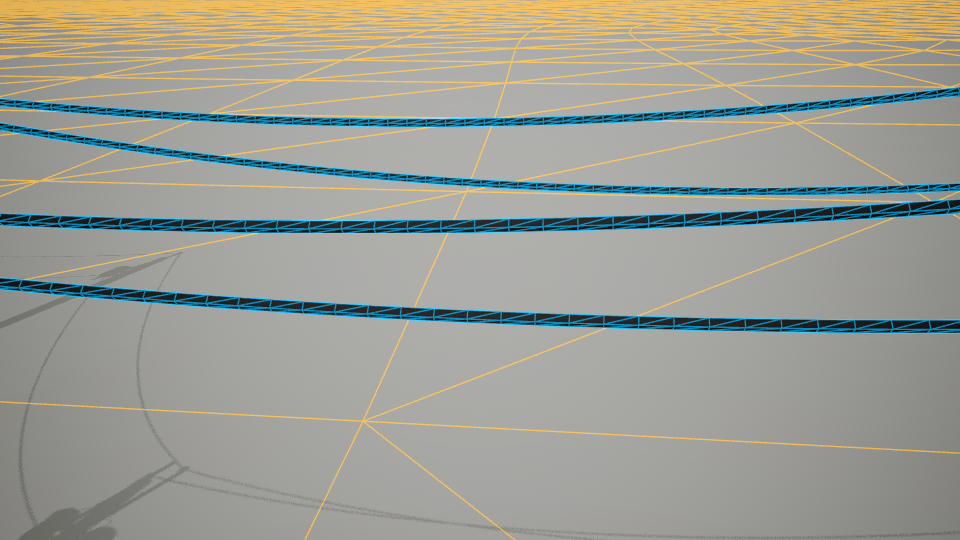
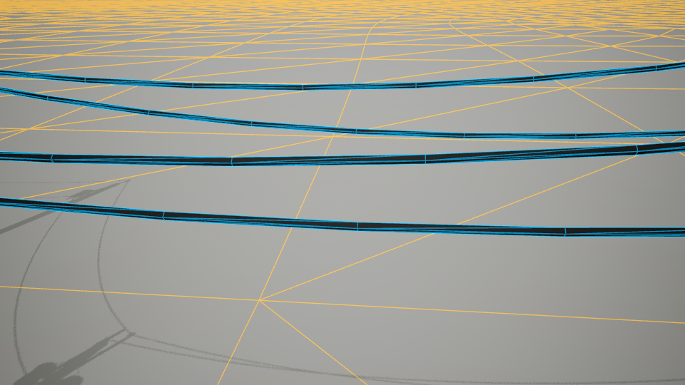
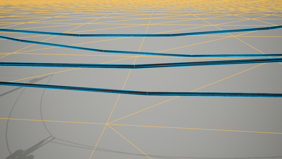
Cable Spacing
Controls the segment length along the cable’s path, affecting both geometric smoothness and UV mapping granularity.
- Minimum: 10 units (creates very dense, smooth cables)
- Maximum: 1000 units (creates very low-poly cables with large segments)
- Impact: Higher spacing values reduce triangle count but may create angular bends; lower values increase smoothness at performance cost.
Visual Comparison:

| Variable | Default | Description |
|---|---|---|
| Cable Radius | 3.0 | Defines the thickness of the cable in Unreal units. |
| Cable Max Draw Distance | 0 | Maximum rendering distance for cable meshes. Set to 0 for infinite draw distance. Note: Works with both procedural and merged static mesh. |
Custom Data Asset
Follow the steps below to create a custom data asset.